Thursday, October 6, 2016

Big Data Analytics for Your Network

The help desk just called. Users are reporting the wireless is down in your office, and nobody can get on the network. The wireless seems fine to you. You're connected. You ask a few people nearby, and they're connected too. You log into the WLC and don't see any problems. Speedtest.net works fine. Maybe you should just turn the controller off and then back on again. That worked last time. No, that's a bad idea. It's the middle of the day and you actually need to troubleshoot it.

After a bit of troubleshooting, you determine the cause of the issue is not the wireless. The DHCP scope is exhausted. Users could connect, but they couldn't obtain an IP address. You shorten the lease time, expand the scope, and call it a day. While you're at it, you wonder if DHCP is the reason connecting has been taking longer than usual, so you fire up Wireshark.

Discover, offer, request, acknowledge. You remember that from a CCNA class half a lifetime ago. Looks good. Well, you think it looks good. It takes about 227 milliseconds from discover to offer. That's normal, right? You realize you're not sure what normal is. You don't know your baseline, and you have no idea how long DHCP should take from discover to offer or request to acknowledge. What about dot1x? Is the RADIUS server slowing things down? You really have no idea. It works. It's lunch time. Nobody is complaining - right now.

Ok, hopefully the way you run your network is nothing like this. However, let's face it: this is an exaggerated version of the reality that many deal with on a day to day basis. There is often little insight into the individual operations that contribute to network performance as a whole. "The wireless is down" could mean any number of things, many of which may be out of the purview of the team managing the wireless network. Troubleshooting is often a reactive process. Even when there is visibility into network operations and baselines are known, it can be difficult to determine if your "normal" is actually optimal.

I recently attended a presentation by Nyansa at Networking Field Day 12. Nyansa is a startup focusing on what they call Cloudsourced Network Analytics. Their goal is to go beyond providing visibility in the form of pretty graphs and actually provide actionable insight about how to improve the end user experience.

Friday, September 9, 2016

Mnemonic: Syslog Severity Levels

Ever have trouble remembering syslog severity levels?


I was organizing some old study notes and came across this mnemonic. It's easy to remember, and I'm sure many network engineers can relate.

Everyone always complains even when nothing is different. 


[E]veryone  [A]lways [C]omplains [E]ven  [W]hen    [N]othing      [I]s            [D]ifferent
[E]mergency [A]lert  [C]ritical  [E]rror [W]arning [N]otification [I]nformational [D]ebugging

Level              Description
0 - emergency      System is unusable
1 - alert          Immediate action needed
2 - critical       Critical condition
3 - error          Error condition
4 - warning        Warning condition
5 - notification   Normal but significant condition
6 - informational  Informational message only
7 - debugging      Appears during debugging only


More information about syslog (system message logging):
https://www.cisco.com/c/en/us/td/docs/routers/access/wireless/software/guide/SysMsgLogging.html

Saturday, September 3, 2016

Spanning Tree Protocol Visualization - Initial Convergence

Spanning tree: everyone's favorite protocol! Thousands of pages have already been written about spanning tree, so I've decided to take a different approach.

I find it helpful to visualize protocol elections and traffic flow in order to better understand protocol behavior, so I created a visualization illustrating the initial spanning convergence process. This visualization only addresses the initial root bridge election and STP convergence process, for example, if all switches were to boot at the same time. This does not address converging a new STP topology after a topology change.

The visualization below is basically an embedded slideshow that can be advanced by clicking on the image. There are notes for each slide that briefly explain each step of the convergence process. The numbers on each side of the links between switches represent the port number of each uplink.

Here are the basic steps of the initial STP convergence process:
  1. Elect the root bridge.
  2. Determine the root ports.
  3. Determine the designated ports.
  4. Remaining ports are blocking ports.

Click the image to advance the visualization. 

Tap here if you are on a mobile device.


As you can see, the resulting topology (the logical forwarding topology that is created after STP blocks redundant links) looks something like an upside-down tree.

Here is an example of of what this tree might look like when redundant links are blocked by STP in a larger L2 topology (although hopefully your network looks nothing like this). The links shown in black can be used, because each port is in the forwarding state. The links shown in red cannot be used, because one of the ports is in the blocking state. Reducing the topology to a tree of forwarding links is how spanning tree maintains a loop free L2 topology.


Once again, this is not meant to be a complete description of STP, but rather a visualization and basic description of the initial convergence process.

Feel free to leave questions or comments below.

Tuesday, August 9, 2016

Opengear and the Evolution and Consolidation of Network Devices

Opengear at Tech Field Day Extra 2016


I recently attended Cisco Live 2016 in Las Vegas and was invited to attend Tech Field Day Extra as a delegate. The first presenter was Opengear, a maker of console access servers and remote management gateways. They describe their products as "next generation Smart Solutions for managing and protecting critical IT and communications infrastructure."


While the term "next generation" is frequently overused, I can't argue with Opengear. Opengear extends the functionality of a console access server into a more complete out-of-band management solution. First, the Opengear presentation made me reevaluate what I should look for in an a console access server. What should it do? What shouldn't it do, and what roles should be held by separate devices?

Friday, February 5, 2016

Configuring ERSPAN on Cisco Routers and Switches

In two recent posts, I covered SPAN, for mirroring traffic to a port on a local switch, and RSPAN, for mirroring traffic across a VLAN to a port on a remote switch.  What if we want to mirror traffic traffic to a destination across a L3 link?  Cisco provides the ability to do this natively with a feature called ERSPAN, or encapsulated RSPAN.  However, this feature is only available on higher end platforms such as Catalyst 6500 and 6800 series switches, 7600 series routers, ASR1000, and CSR1000v (this is not a complete list).

ERSPAN

Like SPAN and RSPAN, configuring ERSPAN is pretty straightforward.  ERSPAN simply requires L3 connectivity between source and destination devices.  The ERSPAN monitor session then builds a GRE tunnel that transports mirrored frames from the source port to the destination port.

Basic ERSPAN configuration is as follows:
! Source switch
monitor session SESSION-NUMBER type erspan-source 
 source-interface INTERFACE(S)|VLAN(S) {TX|RX|BOTH}
 no shutdown
 destination
  erspan-id ERSPAN-ID
  ip address DESTINATION-IP
  origin ip address ORIGIN-IP

! Destination switch
monitor session SESSION-NUMBER type erspan-destination
 destination-interface INTERFACE(S)
 no shutdown
 source
  erspan-id ERSPAN-ID
  ip address SOURCE-IP
    It is important to note that when configuring the destination switch "source IP," you should select the source IP on the destination switch itself - the GRE tunnel endpoint.  Source IP does not refer to the GRE tunnel origin IP address.  Therefore, the "ip address" command should match on the source and destination.

    Below is a basic ERSPAN config to mirror data from R1 interface g3 to R3 interface g3.  I created this topology using VIRL using CSR1000V routers for R1 and R3.


    Saturday, January 30, 2016

    Configuring RSPAN on Cisco Catalyst Switches

    I recently wrote a post on configuring port mirroring (SPAN) on Cisco Catalyst switches.  SPAN (switched port analyzer) allows you to mirror traffic from a source or multiple sources on a switch to a destination interface or interfaces on the same switch.  RSPAN (remote SPAN) takes this a step further and allows you to mirror traffic to an interface on a remote switch or switches.

    RSPAN


    RSPAN configuration is relatively simple and builds upon existing SPAN functionality and configuration syntax.
    • Create an RSPAN VLAN on the source switch, destination switch, and all switches in the transit path.
    • Take traffic from a specified source on switch A, and mirror it to an RSPAN VLAN.  
    • Then, on switch B, use traffic from this VLAN as the source and mirror it to a physical interface

    As shown below, traffic mirrored from the switch on the right to the switch on the left can traverse other switches as long as there is end to end L2 connectivity between them (ie. the RSPAN VLAN exists on all switches).


    Basic RSPAN configuration is as follows:

    Thursday, January 28, 2016

    Configuring Port Mirroring (SPAN) on Cisco Catalyst Switches

    So you have a network issue.  Or perhaps you don't, but you need to help find the root cause of a performance issue and conclusively show that it's not network related.  In either case, packet analysis is your friend.

    At times, it can be convenient (and effective) to capture directly on an affected server or host.  However, you may not always be able to access the affected device.  Even you can, capturing from the affected device is not always the best option due to TCP segmentation offload, checksum offload, and a number of other factors.  (These are outside of the scope of this post, but Kary over at packetbomb.com has a ton of great content on packet analysis including why you shouldn't capture on a host.  See here.)

    A network tap is the best solution when absolute precision is required.  However, this can be impractical and is often overkill.  This is where port mirroring comes into play.  Cisco gear provides a number of ways to mirror traffic from a specified source (or sources) and get frames from point A to point B for analysis. 


    Wednesday, April 8, 2015

    vMotion Fails - Failed to connect to remote host. Network unreachable.

    When migrating a VM using vMotion, the migration may stall at 14% and eventually fail with the following error:

    Migration [xxxx:xxxx] failed to connect to remote host <x.x.x.x> from host <y.y.y.y>: Network unreachable.

    Usually this is a pretty straightforward fix: correct whatever network issue is preventing communication between the vmkernel ports.  However, I recently encountered an issue where the network was configured properly, traffic was flowing, and vMotion still failed.

    Everything with the multi-NIC vMotion config checked out:
    • Two separate VMkernel ports on the relevant vSwitch with IPs on the same subnet.
    • One vmnic active and one standby for each VMkernel port.
    • Active/standby adapters on the second VMkernel port were the inverse of the first.
    • vMotion enabled on the vMotion VMkernel ports.
    • 9000 MTU on each vSwitch and VMkernel port
    • 9000 MTU on the relevant switch and switchports.
    • Relevant switchports tagged for the appropriate VLAN.


    (The configuration is pretty straightforward, as outlined in the VMware KB: kb.vmware.com/kb/2007467)

    Tuesday, March 31, 2015

    ASA Remote Access User Prevent SSH Access

    When configuring a remote access VPN on an ASA, there are times when an external authentication server (RADIUS, TACACS+, etc) is not available.  In this case, the local AAA database can be used:
    asa01(config)# username vpnuser password p@ssw0rd privilege 0
    asa01(config)# username vpnuser attributes
    asa01(config-username)# service-type remote-access
    asa01(config-username)# exit
    asa01(config)#
    You might think that specifying privilege 0 and service-type remote access as shown above would be enough to prevent this user from logging in through SSH.  However, this may not be the case.  Let's look at the following example:
    asa01# sh run user vpnuser
    username vpnuser password jpCK6VfivhvBp0Pn encrypted privilege 0
    username vpnuser attributes
     service-type remote-access
    asa01# sh run aaa
    aaa authentication ssh console LOCAL
    aaa authorization exec LOCAL
    asa01#
    With this configuration, it is still possible for "vpnuser" to log in through SSH:
    vpnuser@asa01's password:
    login as: vpnuser
    vpnuser@asa01's password:
    Type help or '?' for a list of available commands.
    asa01>
    This is possible because the above configuration only specifies AAA authentication, not authorization.  Therefore the local user account's password is checked against the local database, but no check is performed to determine whether or not this local user is authorized for EXEC shell access.  This behavior can be changed by enabling management authorization with the following command:
    asa01(config)# aaa authorization exec LOCAL
    asa01(config)#
    Now if we attempt to log in with this same account, the login will fail:
    login as: vpnuser
    vpnuser@asa01's password:
    Access denied
    vpnuser@asa01's password:

    The ASA configuration guide goes into more detail about this feature here:
    http://www.cisco.com/c/en/us/td/docs/security/asa/asa91/configuration/general/asa_91_general_config/admin_management.html#86134

    Saturday, January 10, 2015

    Choosing an ExtremeXOS Software Release

    When updating ExtremeXOS, it is important to choose your software release carefully.  The newest builds may contain new features that are not yet stable.  I learned this the hard way.  The Extreme support portal currently does not label their software builds with anything that indicates what is a stable build and what is may contain new unstable features.


    Thursday, January 8, 2015

    Extreme Networks EXOS Cheat Sheet

    After working in primarily Cisco or Cisco-esque CLIs, ExtremeXOS can have a bit of a learning curve.  At the time of this post, Extreme Networks' documentation is almost entirely in PDFs.  In my opinion, these are a bit of a pain to navigate and are not well indexed by search engines.

    This post is meant to serve as a basic EXOS cheat sheet.  It is by no means meant to be a configuration guide or thorough command reference.  I will update this post periodically to add additional commands.

    update: I reached out to Extreme regarding their documentation (I work for a partner), and it turns out they already have an EXOS cheat sheet, so my channel SE sent it over.  I was not able to find this document anywhere on Extreme's site.  However, an Extreme SE confirmed this document is public, so here it is:  EXOS Quick Guide - Cheat Sheet.  I may still update this page on occasion, but Extreme's document is more complete.


    Monday, January 5, 2015

    HOWTO: Basic Cisco ASA AnyConnect VPN 8.2(5)

    A while back I posted a how-to for configuring AnyConnect in ASA version 8.3+.  I recently received a request to post the 8.2(5) configuration, so here it is.  The example below uses split tunneling and local authentication.  For RADIUS authentication, see this post.


    Before beginning, verify you have the AnyConnect essentials license (without this license, only two simultaneous sessions are permitted).
    asa# sh ver | inc AnyConnect
    AnyConnect Premium Peers          : 25             perpetual
    AnyConnect Essentials             : 25             perpetual
    AnyConnect for Mobile             : Enabled        perpetual
    AnyConnect for Cisco VPN Phone    : Enabled        perpetual
    asa#
    

    Saturday, December 27, 2014

    HOWTO: Cisco ASA AnyConnect RADIUS Authentication with NPS

    Following up on my previous AnyConnect how-to, this post shows how to configure a Cisco ASA to authenticate against a Windows Network Policy Server (NPS) using RADIUS.

    First, configure a aaa-server group with the radius protocol.
    asa01(config)# aaa-server RADIUS protocol radius
    asa01(config-aaa-server-group)# exit
    asa01(config)#
    Next, specify your NPS server and pre-shared-key.
    asa01(config)# aaa-server RADIUS (inside) host 10.24.12.2
    asa01(config-aaa-server-host)# key pr3-shar3d-k3y
    asa01(config-aaa-server-host)# exit
    asa01(config)#
    
    On your NPS server, launch NPS.


    Wednesday, April 30, 2014

    HOWTO: Basic Cisco ASA AnyConnect VPN 8.3+

    This is a brief how-to style guide for configuring an AnyConnect remote access VPN on an ASA running version 8.3(1) or greater.  The example below uses split tunneling and local authentication.  RADIUS authentication will be covered in a future post. (update: see here)


    Before beginning, verify you have the AnyConnect essentials license (without this license, only two simultaneous sessions are permitted).
    asa# sh ver | inc AnyConnect
    AnyConnect Premium Peers          : 25             perpetual
    AnyConnect Essentials             : 25             perpetual
    AnyConnect for Mobile             : Enabled        perpetual
    AnyConnect for Cisco VPN Phone    : Enabled        perpetual
    asa#
    

    Monday, March 24, 2014

    ASA pre-8.3 vs post-8.3 NAT explained

    In ASA software version 8.3(1), Cisco completely restructured ASA NAT syntax.  Quite a bit has already been written about these changes. However, since this is often a cause of confusion, I will try to provide an explanation of three of the most commonly used forms of NAT on an ASA: dynamic PAT, static NAT, and "nonat."  Below you'll find pre-8.3 and post-8.3 configuration examples with translations into into plain English.  Please feel free to comment if you have any questions.

    What is NAT?


    I'll start with the basics.  NAT stands for network address translation.  It translates the real IP address of a device to the mapped IP and vice versa.

    Real IP: the actual IP address of the device generating the traffic (on the inside interface in the examples below)
    Mapped IP: the IP address the ASA translates the real IP address to (on the outside interface in the examples below).

    NAT is most often used to translate private RFC 1918 IP addresses to publicly routable IP addresses (there are other less common uses as well).

    For example:
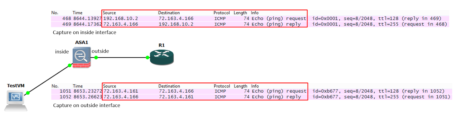
    A ping is sent from TestVM (192.168.10.2) to R1 (72.163.4.166).  In this example, R1 is on the internet, so the ASA cannot route the private address of 192.168.10.2 to R1.  It must NAT the packet.

    We can see this happen in the Wireshark captures below:

    Saturday, March 22, 2014

    ASA Hairpinning and TCP state bypass

    So what is hairpinning, anyway?  Hairpinning is when traffic received on an interface is immediately routed back out the same interface.  If you visualize the packet flow, it looks something like a hairpin:

    The command "same-security-traffic permit intra-interface" allows us to hairpin traffic on an ASA.  The most common use case is allowing remote access VPN traffic to traverse a site to site VPN tunnel as shown in the diagram above.

    However, since we have the ability to hairpin VPN traffic, it seems safe to assume that we can hairpin other traffic as well.

    Let’s look at the following scenario: